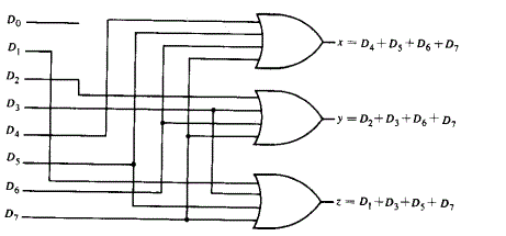
The rf receiver receives the data through rf links and must transmit this data to the arduino. 3 to 8 decoder with truth table and logic gates.we know possible outputs for 3 inputs, so construct 3 to 8 decoder , having 3 input lines, a enable input and 8 output lines. 2 m max., output voltage: The new logi7400ic library provides a logical circuit appearance.; In the below diagram, given input represented as i2, i1 and i0 , all The complete circuit diagram including the transmitter and receiver part for this project is shown in the images below. The rf receiver receives the data through rf links and must transmit this data to the arduino. Logisim 7400 series integrated circuits library. 90±45 ° between a and b (1/4 t ± 1/8 t) rise and fall times of output: Let's write the truth table for the encoder using the information that the encoder gives outputs that are physical addresses of the inputs. In the below diagram, given input represented as i2, i1 and i0 , all 13.11.2017 · arduino + dht11 + lcd connection circuit: This library aims to be a comprehensive 7400. To complete the traffic light controller, we just need to make the inputs i 0 and i 1 cycle through the binary representations of the numbers 0¼3. There are two variants of the library with different circuit appearances available: In the classic logi7400dip library, the circuit appearance reflects the physical pin layout of the dip packaged chips.; 2 m max., output voltage: The vcc and gnd pins of the receiver module are connected to 3.3v and ground pins of the arduino. The rf receiver receives the data through rf links and must transmit this data to the arduino. 2 m max., output voltage: 3 to 8 decoder with truth table and logic gates.we know possible outputs for 3 inputs, so construct 3 to 8 decoder , having 3 input lines, a enable input and 8 output lines. The vcc and gnd pins of the receiver module are connected to 3.3v and ground pins of the arduino. Vcc (+5v), data, nc(not connected pin) and gnd (from left to right). As show in the circuit schematic the dht11 sensor has 4 pins: Circuit diagram of rf transmitter and receiver: 3 to 8 decoder with truth table and logic gates.we know possible outputs for 3 inputs, so construct 3 to 8 decoder , having 3 input lines, a enable input and 8 output lines. 10.10.2018 · an 8:3 encoder has eight input lines and three output lines. The rf receiver receives the data through rf links and must transmit this data to the arduino. Vcc (+5v), data, nc(not connected pin) and gnd (from left to right). 2 m max., output voltage: This library aims to be a comprehensive 7400. Logisim 7400 series integrated circuits library. 90±45 ° between a and b (1/4 t ± 1/8 t) rise and fall times of output: Our interfacing circuit diagram is shown below. The new logi7400ic library provides a logical circuit appearance.; We no longer have to think about the problem of invalid inputs being presented to the circuit. Let's write the truth table for the encoder using the information that the encoder gives outputs that are physical addresses of the inputs. 13.11.2017 · arduino + dht11 + lcd connection circuit: Hence, the data out pin of the receiver module must be connected to digital i/o pin 11 of the arduino. The complete circuit diagram including the transmitter and receiver part for this project is shown in the images below. 3 to 8 decoder with truth table and logic gates.we know possible outputs for 3 inputs, so construct 3 to 8 decoder , having 3 input lines, a enable input and 8 output lines. In the below diagram, given input represented as i2, i1 and i0 , all The new logi7400ic library provides a logical circuit appearance.; The vcc and gnd pins of the receiver module are connected to 3.3v and ground pins of the arduino. Our interfacing circuit diagram is shown below. 90±45 ° between a and b (1/4 t ± 1/8 t) rise and fall times of output: 13.11.2017 · arduino + dht11 + lcd connection circuit: To complete the traffic light controller, we just need to make the inputs i 0 and i 1 cycle through the binary representations of the numbers 0¼3. The 10k variable resistor is used to control the contrast of the lcd … This library aims to be a comprehensive 7400. In the classic logi7400dip library, the circuit appearance reflects the physical pin layout of the dip packaged chips.; Circuit diagram of rf transmitter and receiver: The rf receiver receives the data through rf links and must transmit this data to the arduino. 10.10.2018 · an 8:3 encoder has eight input lines and three output lines. 8 To 3 Encoder Circuit Diagram : Priority Encoder And Digital Encoder Tutorial :. Logisim 7400 series integrated circuits library. Hence, the data out pin of the receiver module must be connected to digital i/o pin 11 of the arduino. 10.10.2018 · an 8:3 encoder has eight input lines and three output lines. 90±45 ° between a and b (1/4 t ± 1/8 t) rise and fall times of output: There are two variants of the library with different circuit appearances available:
90±45 ° between a and b (1/4 t ± 1/8 t) rise and fall times of output:

13.11.2017 · arduino + dht11 + lcd connection circuit:
The new logi7400ic library provides a logical circuit appearance.;
8 To 3 Encoder Circuit Diagram : Priority Encoder And Digital Encoder Tutorial :
on Jumat, 19 November 2021

Tidak ada komentar:
Posting Komentar